Revit How to Continued Arrow Dimension Stringers
This guide takes a deep dive into Revit dimensions. You will learn the difference between the different types and you'll master the type properties to create all dimensions you need.
Check out this live session:
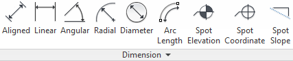
There are multiple types of dimensions in Revit. In this post, we'll focus on the Aligned type, which is the most commonly used. However, the features are similar from one dimension type to another.
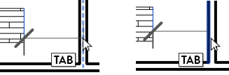
Before going through advanced dimension parameters, let's do a quick overview of the basic features. Create an aligned dimension by using shortcut DI. You must click on references to create the dimension. Use the tab key to cycle between close references.
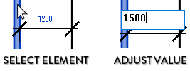
When you click on a dimensioned element, the value becomes blue. Change the value and the element moves
Dimensions can be used with multiple references. Click a point in the white void to complete the dimension. Use the Edit Witness Lines tool in the contextual tab to adjust the references.

2- Understand Dimensions Type PARAMETERS
For the Aligned Dimension type, there are 42 type parameters. That's quite a lot! Let's go through them.

3- Understand Continuous vs Baseline vs Ordinate
The first parameter that can be modified is Dimension String Type. There are 3 options: Continuous, Baseline and Ordinate. In the image below, you can see the difference between the types. In the next pages, we'll focus on the Continuous option, which is the most commonly used.

4- Set WITNESS & DIMENSION LINES OPTIONS
Dimension Line Extension refers to extension lines perpendicular to the elements being dimensioned.

Witness Line Extension refers to exterior extension lines parallel to the element being dimensioned.

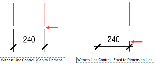
Witness Line Control: There are two options: Gap to Element lets you decide the distance between the element and the witness line. Fixed to Dimension Line lets you set a specific length for the witness line.
Witness Line Gap to Element controls the default distance between the dimensioned element and the witness line. Only available if you use the Gap to Element option.
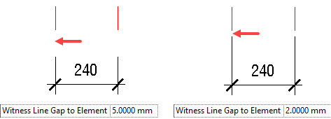
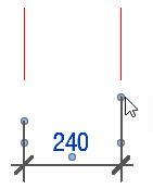
This is the default distance. It is possible to customize this value of each dimension instance by selecting the dimension and dragging the blue dots of the witness line.
Witness Line Length: When the Fixed to Dimension Line option is selected, you set a specific line to the entire witness line. Distance to the element doesn't matter.

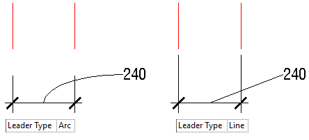
Leader Type: pick between arc and line. The leader only shows up if you move the dimension value away.
5- Set Tick Mark STYLES
In the next tip, you'll learn how to assign tick marks. But first, you need to learn where to find these styles and create your own.
Go to the Manage tab. Click on Additional Settings. Under Annotations, select Arrowheads.

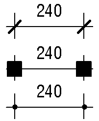
Here, you can see all styles available in your project. You can create a new style by duplicating an existing one. Here are examples of tick marks you could create and use:
6- Set Tick Marks
Now that you've created multiple tick mark styles, you can assign them. There are 4 different mark parameters you can set.
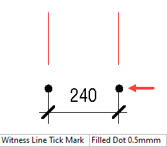
The first is the Witness Line Tick Mark, which is placed at the extremity of the witness line. This isn't used very often.
Then, there is the main Tick Mark parameter. This is the tick you are most likely to use. You can see two different options below.
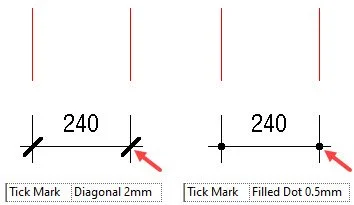
Notice that in case of a line being used, you can set the width of the tick with the Tick Mark Line Weight parameter.

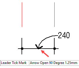
Then, you can set a Leader Tick Mark. It only appears if you drag the value away from the dimension.
7- Set Centerline Options
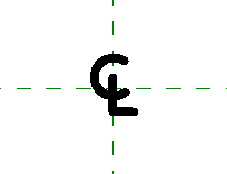
The centerline options automatically appear when you dimension an object based on its center. For example, we dimension a round family with a witness line in the center. Three parameters can be used here: The Centerline Symbol, with the CL letter. Then, the Centerline Pattern, which is a dash. Finally, the Centerline Tick Mark, which is a filled box.
The centerline visual settings are only active when the dimension witness lines are referring to the center of an element. The other parameters use the standard settings.

The Centerline Symbol is a loadable generic annotation .rfa family.
8- Set INTERIOR TICK LINES
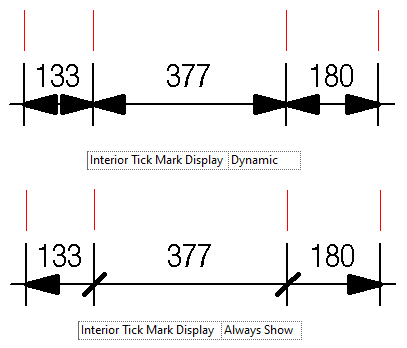
The Interior Tick Mark appears whenever you have three or more witness lines. The extremities use the Tick Mark option, while the interior references use the Interior Tick Mark.
As you can see below, we use an arrow tick mark with diagonal lines for the interior.

There is an option called Interior Tick Mark Display. The Dynamic option will typically ensure that the Tick Mark value is used everywhere, including for the interior marks. Use the Always Show option to display the Interior Tick Mark you've selected.
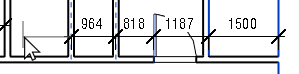
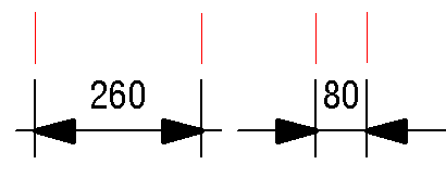
9- The "Arrows" TICK MARKS Automatically Reverse When DimensionS ARE Too Small
If the arrows are too tight, they will automatically reverse and place themselves on the exterior side of the dimension instead.
Arrows will not display if they are used in the interior and if the dimensions are too tight.
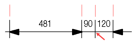
This behavior is specific to Arrows tick marks. For some reason, you cannot select an arrow tick mark for the Interior Tick Mark.
10- Set Dimension Color
In the type properties, you can switch the dimension's color. It has an effect on the entire dimension: the witness lines, the tick marks, the leader, the text, etc.

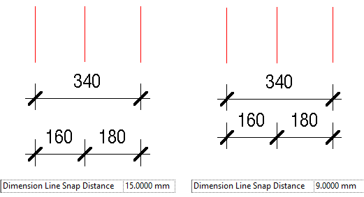
11- Set Dimension Snap Line Distance
Dimension Snap Line Distance controls the default distance between two dimensions. Revit will "snap" the dimension in place at this distance. You can always "override" the snap and move the dimension beyond this specific location.
12- Set TEXT OPTIONS
Setting the text options is quite straightforward. Here are the 12 options you can set:

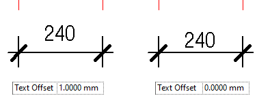
While most of these parameters are self-explanatory, some of them deserve further clarifications. The Text Offset controls the distance from the dimension line to the text:
Text Location lets you decide between Inline and Outline. This refers to the leader line, which will either be below the text or next to it.

Show Opening Height name isn't quite accurate. It doesn't display the "opening height", but simply the height of the dimensioned element. For example, it will display 600mm for a window with a height of 600mm.
This dimension only shows up when dimensioning elements with a height parameter. The dimension must be placed on the precise width of the element to display the height.

Read Convention is used to indicate how the text should be displayed for vertical dimensions. Typically, Up, then Left is the acknowledged graphic standard. Try other options if you want.

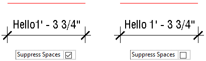
Suppress Spaces controls if there is a space between the number value and the prefix/suffix. Only has an impact if prefix and/or prefix are used. Check out tip #14 for more info.
13- Set Primary And Alternate Units
Let's explore the units options. First, you need to set up the primary units. Typically, this uses the project settings.
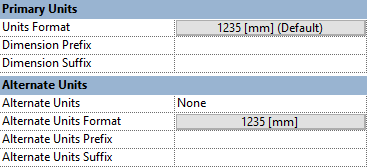
You can override the primary units. For example, you could decide to set additional decimal for more precision and add the unit symbol.

Then, you can set a Secondary Units. In this example, use Fractional Inches. For clarity, we will use brackets for prefix and suffix. We then set the value to display Below.

Since Revit 2022, you can set up a prefix and suffix for the main units. For example, you could use the ± symbol in the type properties.

14- Set EQUALITY VALUES
When you have multiple segments, the EQ button appears. If you click it, the distance will become equal between the segments and the = symbol appears.

In this example, we use a different Equality Text symbol.

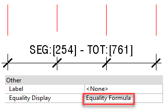
You can customize not only the symbol used, but also apply an Equality Formula and adjust the Equality Witness Display. With the formula, you can show different values, for example: total length, segment length, and amount of segments. You can set up prefix and suffix. In the example below, we want the dimension to show both the total length and segment length of the EQ dimension.

However, for these parameters to show up, you'll need to change the instance properties of the dimension. In the Equality Formula parameter, switch from Equality Text to Equality Formula.
Be careful: putting too many constraints on your model can cause performance problems. A good idea is to apply the EQ feature but immediately remove it. You can still display the EQ symbol if you switch the Equality Display instance parameter to "Equality Text". The symbol will display as long as the values are equal.
15- SET TEXT AROUND DIMENSION VALUE
It is possible to set text overrides around your dimension. You have to double click on the number value. Enter your text.

It is also possible to completely replace the number value for a text value.
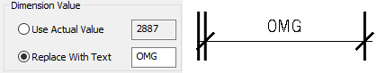
You cannot use a number override here. No, we won't tell you how to put a "fake" dimension because we don't want to be responsible for bad practices that cause costly construction errors.
16- AUTO-DIMENSION WALLS
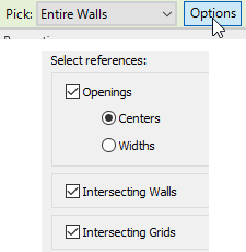
There is a tool that most people don't know about. It lets you auto-dimension all the openings, intersecting walls and intersecting grids in a single click when placed on a wall. When placing the dimension, use the Entire Walls option in the Options bar. Click on Options and select which elements you want to include.
When done, select the wall you want to auto-dimension. As you can see below, the entire dimension is created in a single click.

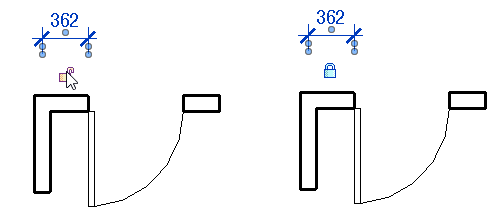
17- Constrain Elements
It is possible to click on the lock icon to constrain the dimensioned elements together. When one of the element moves, the other will move as well. Be careful: too many constraints can slow down your models.
Learn how to use ordinate dimensions and automate dimensions with Dynamo in our new DIMENSIONS bonus guide, which is available in the 3-packages bundle.
Source: https://revitpure.com/blog/17-tips-to-master-dimensions-in-revit
Post a Comment for "Revit How to Continued Arrow Dimension Stringers"